Setting up and managing an EVA – HP StorageWorks EVA – HP StorageWorks Enterprise Virtual Array – 4100 – 4400 – 6100 or 8100

In this document we will see in detail all the hardware of these controllers, Disk Cases and Fiber Switches. Later we will configure an EVA 8000 new, Creating a New Disk Group, Creating Virtual Disks, adding hosts and presenting these virtual disks to the hosts. We will also update the firmware, We will create snapshots, Snapclones… all this from HP Command View.
How it's hard to get hold of a record cabinet to learn, There are utilities that allow us to emulate this hardware with software. In the case at hand, This document has been made with him, since it is practically impossible to make a complete document with a physical disk enclosure (for its cost). You can download the HP EVA Simulation v.2.0 – HERE To practice.
Introduction – HERE
Hardware Description – HERE
Setting up an EVA – HERE
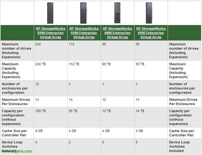
Well, This document will explain how to assemble a disc array with all its components, both hardware and software. It will be an EVA cabin, or also calls: HP StorageWorks 8100 Enterprise Virtual Array, HP StorageWorks 6100 Enterprise Virtual Array, HP StorageWorks 4400 Enterprise Virtual Array and HP StorageWorks 4100.
More info: HTTP://h20000.www2.hp.com/bizsupport/TechSupport/Document.jsp?objectID=c00365590

In this graph we can see the different EVA that HP gives us, The functionality in all of them is the same, The only thing that differentiates them is the specifications, that have more capacity, More Albums, More cache…

This will be the overview of the rack, from our closet where we have our EVA, This is, The two controllers, Disk Cases and Fiber Switches. We have three views, The front view of the rack, we also have the rear view to see what your hardware is like and we have the important part of the cabling, to see how we'd have to wire it.
More info: HTTP://h20000.www2.hp.com/bizsupport/TechSupport/Document.jsp?objectID=c00365594
Let's take a closer look at each part of the EVA,

This is the record case or “Disk drive enclosure” being the front view and its components. Has 14 para bays 14 Hard Drives. And we have three front LED's:
– EMU Status Indicator: This green LED shows the heartbeat status of the EMU (Environmental Monitoring Unit).
– Power Indicator: The LED is green when +5 VDC and +12 VDCs are correct (Virtual Display Client)
– Enclosure Indicator: This LED will normally stay off. When there is a problem this LED will light up.

GOOD, we continue with the record box or “Disk drive enclosure” being the rear view and its components. We have three parts:
– EMU (Environmental Monitoring Unit): On the left, is what will inform us of the status of the record drawer, provides us with additional protection for catastrophic failures. EMU detects conditions such as power failures, Fan failures, High internal temperatures, External temperature sensors; communicating all these conditions to the controllers. Its components are as follows:
+ EMU Status & Heartbeat Indicator: HeartBeat status indicator, is a green flashing LED.
+ Enclosure Power Status Indicator:The LED is green when +5 VDC and +12 VDCs are correct (Virtual Display Client)
+ Enclosure Fault Indicator:This LED will normally stay off. When there is a problem this LED will light up.
+ Alphanumeric Status Display: It is a two-character display, Displays the functions and statuses of the enclosure.
+ Function Select Push Button: The main function of this button is to select a function from the previous screen. The indicator will stay on when there is an error.
+ Display Group Select Push Button: This button is used to see the groups of options that we have on the screen, or to adjust the control of the audible alarm.
+ RS232 Only Connector: For HP Staff Use Only.
+ LCD Only Connector: Not used.
+ CAB Only Connector: Used for EAB (RJ45 connector). It is a connector of the address bus with the controller.
+ Main functions of the EMU:
.- Using ESP (Enclosure Services Processor) to control CSE (Enclosure Services Interface) and communicate with the controllers.
.- Assign the Disk Drawer Number (In).
.- Show the bay 1 loop ID.
.- Monitor drawer operation.
.- Dectectar, report, Record and display conditions.
.- Show EMU status, of the drawer and its elements.
.- Implement automatic corrective actions for certain conditions.
.- Display drawer status data to controllers.
.- Display the WWN and logical address of all hard drives.
– I/O Module A and B: The drawer has two I/O modules, A and B, These are responsible for routing read and write traffic to disks, using loop A and loop B in a dual loop configuration. They are each connected to a fiber switch and thus communicate with the controllers. Both modules are of identical functionality, but they cannot be exchanged, module A always on the right and module B always on the left. Its components:
+ Power Switch: Ignition connector.
+ Copper Cable: Copper Wire.
+ Port1 Status LED: Displays port status 1.
+ Power Status LED: If it is on, it means that it is getting power.
+ Port2 Status LED: Displays port status 2.
+ Loop A/B Input & Output Port – Upper port & Lower port: Each module has two data input and output ports, are the ones that connect to each controller or each fiber switch.
– Power and ventilation supplies: It has two power supplies at the back of the drawer. These are self-adjusting and are for specific countries, AC input voltage 202 a 240 VAC ±10%, 50 To 60 Hz, ±5%, (188 a 264 VAC, 47 a 63 Hz). The power outputs are as follows:
+ 5.1 VDC for EMU, I/O module, circuit board and disk drives.
+ 12.1 VDC for Hard Disk Drives.
+ 12.1 VDC for Hard Disk Drives.
Its components are as follows:
+ Blower 1/2 Status LED: Displays fan status
+ Blower 1/2: Fan or exhaust fan.
+ Power Supply 1/2: Power Supply.
+ Power Supply Cable 1/2: Power Cord.
More info: HTTP://h20000.www2.hp.com/bizsupport/TechSupport/Document.jsp?objectID=c00365591

GOOD, This is the fiber switch, The top image is the front view of one of them and this bottom image is the back. This will be where we will connect the fiber cables of the record cases, the controllers or our servers (the SAN network – Storage Area Network) to HBA's. All in duplicate, both cabling and switches. The following components are distinguished:
– Network Port: Network Port.
– Port Bypassed Indicator: If the LED is on, indicates that the port is in bypass mode.
– SFP Status Indicator: If the LED is on, it indicates that everything is tight, that there is a connection.
– Port: Fiber Port.
– Power Supply Cable: Power Cord.
– POST Fault Indicator: When the amber LED lights up, it means that some error occurred in the self-test and the change will not work.
– Over Temp Indicator: When the amber LED lights up, it means that the ambient temperature has exceeded 40 ºC. The problem should be fixed until the LED is turned off.
– Power Indicator: When the green LED is on, it indicates that the switch is connected and the internal power is working.
– Loop Operational Indicator: When the green LED lights up, it indicates that the Fibre Channel loop has finished initialization and is now up and running.
More info: HTTP://h20000.www2.hp.com/bizsupport/TechSupport/Document.jsp?objectID=c00365592
More info: HTTP://h20000.www2.hp.com/bizsupport/TechSupport/Document.jsp?objectID=c00365595

These are the controllers, the EVA's. In the image above you can see the front view and in the image below the rear view with all its components.
Description of the front of the controllers:
– WWN and Checksum Label: World Wide Name refers to a unique identifier in a fiber optic storage network or SAS. Each WWN is a number of 8 bits derived from OUI (The first three bits) and information provided by the company. Checksum is a form of redundancy control.
– Blower Compartment: This is the hole where the controller fan is located.
– Alphanumeric Display: It is the screen where we can configure certain parameters/orders from the OCP control panel.
– Operator Control Panel (OCP): The OCP is the one that provides us with a direct interface to each controller. We can see the system status and configuration information, We can turn off the storage system or manage the password. HP Command View EVA is used to manage controllers, however, if we do not have a Command View installed on any server, we can always use the OCP.
– OCP Push Buttons: These are the buttons with which we will move within the OCP, They will be used to enter data or navigate through the menus. The buttons are: Up, Down, Left, Right, Esc and Enter.
– Fault Indicator: Fault/Error Status Indicator/LED.
– Controller Indicator: When the LED flashes everything works fine (The Hearbeat), the problem would be when this LED won't blink.
– Physical Link Indicator: When this green LED is lit it means that there is a physical connection between the storage and a host, this is normal operation. The problem is when this LED is off, which means that there is no physical connection between the storage and any host.
– Virtual Link Indicator: When this green LED is lit it means that all the virtual disks that are presented to the hosts are in perfect working order. When the LED is amber, it means that there is a virtual disk that is not working well. When the LED is off it means that there are no virtual disks presented to the hosts.
– Cache Battery Assembly Status Indicator: When the LED is off, The battery is charged, when the LED is on the battery is charging.
– Unit ID: This is the front and rear blue LED that helps us find a specific controller. It is useful when we have many controllers and we need to know which one we should carry out the operation we are going to perform. Can be activated from the View command.
Description of the rear of the controllers:
– Mirror Port Status:
– Mirror Port x:
– Host Port Status LED:
– Unit ID:
– Power Switch:
– Power Supply:
– Power Supply Cable:
– Host Port FPx – Fibre Channel Cable:
– UART Port:
– UPS Port:
– Copper Cable – Directly Connects the Controllers:
– Loop Xx Status LED:
– Loop Xx:
– EAB to Controller Pair “And” Cable:
– SCSI Cable:
More info: HTTP://h20000.www2.hp.com/bizsupport/TechSupport/Document.jsp?objectID=c00365593
GOOD, Once all hardware racked, Finished wiring, The disks in the drawer we can start the controllers. To do this, we will first give electricity to the controllers and the disc drawers. To turn on the controllers we will press the button “Power Switch” on the back of each.

GOOD, Well, once they are lit and if it is the first time we turn them on, we must enter the name WWN (WorldWide Name) on the display using the buttons of the OCP and press ENTER when it is.

Now we must enter the WWN checksum in the same way with the OCP buttons and pressing ENTER to finish.

We wait for it to start…

We are still waiting for the controllers to start…

GOOD, it is already booted but the system is not initialized, We will initialize it now during system configurations.

We open a browser to the IP address of the EVA, We'll use https and we'll log in. Ideally, you should have HP StorageWorks Command View EVA installed on a server, but if we do not have it installed we connect to the URL of the EVA System Management and from there we will open the Command View.

In the left menu, we have a link to manage controllers with the HP StorageWorks Command View EVA, So we click on “Command View EVA”.

The first thing is to keep the firmware of the controllers up to date, So before you set anything up, We click on the “Code load”,

We confirm that we are going to update the firmware of the two controllers and that they will be rebooted, Accept.

GOOD, Now we have to explore with the “Browse” and find the file that updates both controllers. Previously we will have downloaded it from the HP Software website & Drivers (HERE) and click on “Next step” to continue.

We confirm again that we will update both controllers. “Accept”,

“Next step” Again,

We must accept, This is a warning message to check that it is a firmware that we are going to install, it is a more recent one than the one we have installed and if we are sure to install it, “Accept”,

“Accept”,

… We wait while we install the firmware on this controller…

“Finish” In principle, the firmware installation seems correct.

We must be careful not to turn off the controller at this time, as firmware code may still be uploaded to the controller, “Accept”,

Once the firmware is already installed, We must initialize the controller to put it into operation, Click on “Initialize”,

We accept to initialize the controller, from now on it will delete the contents of the disks where we create a group of virtual disks. It's normal, Since my controller is new, we just put the disks in and put all the hardware in, so it comes without initializing, “Accept”,

Enter the name of the controller in 'STEP 1: Enter a Name', and in 'STEP 2: Enter the number of disks’ Enter the number of physical disks with which we want to create the first group of disks. Pressed “Advanced options” to continue,

In 'STEP 3: Select a drive type’ Mark “Online” (It is a high-capacity, high-performance type). In 'STEP 4: Set the system date/time', We indicate how to set the time we want. “Next”,

In “STEP 5: Resquest a disk failure protection level” It is an additional system to prevent data loss, if we can later create different types of RAID with this disk group, Now we can add an extra disc or two in case one of them breaks down. Select the option that interests us (None, Single or Double), “Next”

In “STEP 6: Enter a Console LUN ID” is where we will indicate an ID to this group of disks that we are created, it is important to look closely at the ID for future configurations. We can also add comments to know what this group of discs is for. “Finish” to create it.

We get a message indicating that the system will be initialized with the configuration we have indicated, If it's correct we accept,

… We wait while the process is completed…

“OK”, and only “OK” 😉

We can see in the summary that we already have a disk group’ with 8 albums in it and that we have left 76 Discs to use.

Once we have a group of disks we can create virtual disks, which is where our servers will work, where we can save our data. So let's go to the 'Virtual Disks' section’ and from there we can create virtual disks and directories to better organize them, So we first created a directory to put the virtual disks inside. Click on “Create folder”,

In 'STEP 1: Enter a Name’ We enter the name of this directory and a comment optionally. Click on “Finish”,

… we wait while the directory is created…

“OK”,

Once inside the directory that we have just created, we are going to create an example virtual disk. So we click on “Create Vdisk”,

In “STEP 1: Enter a Name” Enter the name of the virtual disk, in 'STEP 2: Select a disk group’ we must select the disk group where we want to put this LUN that we are creating. So as before we have created a group of discs with 8 Disks, we will see that we will have it there with the available capacity. In 'STEP 3: Select a Redundancy level and Size’ we will select the level of protection we want at the RAID level, We have three options, RAID0 (Vraid0), RAID5 (Vraid5) o RAID1 (Vraid1), indicating the free space that would be left if we use that level of protection; and we choose the capacity that we are interested in this LUN having, in my case 80Gb (in 'Desired Size'). In 'STEP 4: Select a host’ is to present to a server, but I haven't discharged them yet, So we keep pressing “Advanced Options”,

In 'STEP 5: Select a LUN Address’ We leave as 'No LUNs Avaliable', This will indicate the default value starting from the lowest (of the 1 to the 255). In 'STEP 6: Select a path preference and mode’ select the path or path that we want this LUN to use (Path A-Failover only, Path A-Failover/failback, Path B-Failover only or Path B-Failover/failback). In 'STEP 7: Enter the OS Unit ID’ we will indicate the ID to the LUN, this is more from Solaris, Tru64… for Windows we will not indicate anything, we leave the ID a 0. “Next step”,

In 'STEP 8: Select a Write Cache policy’ We will select our writing policy (Write-back or Write-through), the first is deferred writing and the second is immediate or direct writing (More info HERE). In 'STEP 9: Select a Mirror Cache policy’ We will indicate whether we want the cache to have a mirror as well or not. In 'STEP 10: Select a Read Cache policy’ (On: Deferred or Off writing: Direct writing), “Next step”,

In 'STEP 10: Set write protection’ we will indicate if we want it to be a read-only LUN ('Read only') or a LUN where data can be written ('Read/write'). In 'STEP 11: World Wide LUN Name’ of the virtual disk in the format: 6xxx-xxxx-xxxx-xxxx-xxxx-xxxx-xxxx-xxxx-xxxxx we can put it in by hand, but it is advisable to leave it by default. “Next Step”,

We can put some comments (optional) and click on “Finish” to create the virtual disk or Vdisk or LUN.

… We wait as long as you believe it…

“OK”,

We can create an exact image of a LUN in case we need to make a backup or copy only its contents, the ideal is to take a photo of it or also called a 'snapshot'. To do this,, On the virtual disk we select the option “Create Snapshot”, apart from if we create another snapshot later, You will only copy the changed information to us,

In 'STEP 1: Enter a Name’ We indicate the name of the snapshot, we can use variables like '==Current date-time==’ to give more exact information of when the snapshot is, Click on “Advanced options”,

We select whether we are interested in creating redundancy or not, With some Vraid. In 'STEP 5: Select an allocation policy’ we can choose between 'Fully-allocated’ (Inefficient space) o 'Demand-allocated’ (Space efficient), “Next step”,

Select whether or not we want a read cache policy in 'STEP' 7: Select a read-cache policy’ (On or Off), “Next step”,

IDEM than previously, “Next step”,

Click on “Finish” To create this snapshot,

… and wait while you create the copy of the LUN…

“OK”,

We can see that we already have a snapshot in the left side view.

GOOD, Now let's create the hosts, This is, servers that are connected to fiber switches, to later present the LUN's to the hosts, and that each host sees their LUN and not the ones they should not see for greater security. As many hosts are created as there are connected servers we have. First before creating the hosts I will create directories to organize them in them, so in Hosts, Click on “Create folder”,

We indicate a name and “Finish”,

… We wait while you create the directory…

“OK”,

Now, Within the directory we will create a new host, Click on “Add host”,

We indicate the name of the server we want to add, it will usually be the same name as the server (To avoid trouble), we provide your IP address, and we look for his WWName from the 'Port WW Name' combo, will be the World Wide Name of one of its HBA's, later we will add the other WWN if you have more. Select your operating system in 'Host OS', and click on 'Add Host’ to create it,

… we wait while it is created…

“OK”,

This would be the Host, We can see it from the side panel as well.

If we want to add more WWN ports, because the most normal thing is that he has at least one other, from another HBA, click on the 'Ports' tab’ and we'll add the port from 'Add port',

We unfold the combo and select the WWN from your other adapter (Your WWID). And we click on “Add port” to create it,

… we wait while it is modified…

“OK”,

Now that we have at least one host, if we want this host or server to be able to see a LUN or a Vdisk we will click on the 'Presentation' tab’ and then click on the “Present”,

Select the host or hosts that we want to present to a LUN and click on “Assign LUN”,

Select the ID of the LUN we want to present to it and click on “Finish”,

… We wait while you save your changes…

“OK”,

And we can already see in the properties of this host the Vdisks that it has access to, name and ID.

In addition, We can create Snapclone's, this is the same as a snapshot but the difference is that this copies the entire LUN, even if it's not complete, occupies the same as the source LUN. To create a Snapclone, We click on the “Create Snapclone” from the Vdisk properties. And we'd follow the assistant.

We have more options, If we're going to “Agent Options” And there we have “Discover storage systems”, We can force it to refresh and scan the storage systems again, in case you don't see an album…

It takes a few seconds while it refreshes and we press “OK”, We could already go check if you see the new hardware.

In “Storage system password access” is where we can assign a password to the controllers.

Within this option, We can enable a password ('Enable'), disable it ('Disable') or change it ('Change').

By enabling the password, This is where we would indicate what the password is & “OK”.

In “Licensing options” we will administer EVA licenses,

We can see the current license ('View previously entered license keys') or put in a new one ('Enter new license key'),

This would be the license I currently have, One demo.

In “User interface options” we can change certain points of the appearance of the Command View,

For example, whether or not we want to use configuration wizards ('Use wizards for creating Vdisks and adding hosts'), or the trees, how many maximum objects they will show us in the view, ('Tree objects displayed'), or the S.O. of hosts ('Default operating system for new hosts')…

More, if we go to the menu on the left, We will be able to observe the hardware configuration of our environment, of the EVA. We see that it says 'Rack 1', This is our rack cabinet, if we have several, the normal thing is to rename them to recognize them more easily. Inside each rack we will have the controllers ('Controller') and the record cases ('Disk Enclosure'), and inside the record cases, then the disc bays (with or without a hard drive) or 'Disk Bay'.
The normal thing is to configure the names to our needs, Rename each section to avoid confusion problems.

These would be the properties of one of the disk controllers itself (EVE), The tab “General” detailing her status.

On the “Hosts Ports” We'll see the status of the fiber connections of the connected hosts,

On the “Device Ports” We see the state of the ports.

And on the “Enclosure” We see the state of the drawer itself, of the controllers, Temperatures…

If we are going to “Disk Enclosure X” In the left menu we can see the status of the record drawers, on the “General” we see the World Wide ID, The name, EMU status, alarm…

On the “Power” We can see the status of the two power supplies it has…

On the “Cooling” We will see the state of the discs through the sensors, temperatures and possible alarms.

On the “I/O-Comm” we will see the status of the I/O modules as well as the fiber ports.

Finally, if we are going to “Disk Bay X” In the left menu we can see the status of the disk bays, their positions, this in the “Disk Bay”,

And finally we can check in more detail in the tab “Disk drive” the hard drive that's in that bay, We will be able to provide all of your information.
www.bujarra.com – Héctor Herrero – Nh*****@*****ra.com – v 1.0